Detecting a Jeep Grand Cherokee's Communication Faults
I received a call from a good friend of mine named Tony. It seems Tony was faced with a 2015 Jeep Grand Cherokee 3.6L, suffering from communication network faults that would leave the electronically shifted transmission in ‘PARK.’
Hip to the knowledge that the transmission is shifted electronically, Tony chose the wise, efficient path of fetching a health report, including a DTC scan for the entire vehicle. We learned on a similar vehicle that communication faults need special attention and a well-thought-out plan to ensure efficiency.
Developing the Diagnostic Game Plan
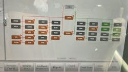
The DTC report showed failures flagged in multiple nodes of the CAN_C bus (Figure 1). A total of 57 DTCs were stored throughout the nodes of the CAN_C bus. At that point, each and every one of the nodes could’ve been suspected. However, I never hang my hat on one piece of data. It is simply one piece of a larger puzzle. We need more puzzle pieces.
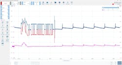
I advised Tony to capture CAN_C bus activity with his 4-trace lab scope. This will allow us to not only witness the failure but also hope to gain an edge on the nature of the fault. In BLUE and RED is CAN_Hi and CAN_LO respectively. The PINK trace represents a math channel, configured to add the RED and BLUE traces together mathematically. At any given point the CAN_C traces should total “5V”, regardless of their state of function. This is represented by a straight pink trace.
As can be seen here, the PINK line deviates across the duration of the screen and does so in a couple of different ways (Figure 2).
- CAN_HI and CAN_LO both saw an increase in voltage by the same amount
- When recessive, both CAN _HI and CAN_LO rhythmically pulsed/decayed in amplitude over time
Logic should tell you that a media (wiring) issue can’t likely create faults like this. This puts a defective/malfunctioning node at the top of the list for suspected failures. With this at the forefront of our minds, Tony and I proceeded to reach for another puzzle piece so triangulation of the fault location could allow us to pinpoint test.
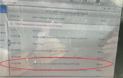
A review of the 10 pages of stored DTCs was carefully carried out. We were in search of clues for a likely suspect node creating the communication fault. Suddenly a valuable clue narrowed the potential for any one of the 20 possible faulted nodes to just two (Figure 3).
Adding Up the Clues
The Transmission control module (TCM) set a DTC U11E3-00 pertaining to a loss of communication with the Electronic shift control module. That would explain why the vehicle would not shift out of ‘PARK.’ However, and more importantly, this TCM communicates with the ESM on both the CAN_C and the CAN_D-PT. My point is that we now realize that the TCM or the ESM are two nodes, very high on the suspect list as they are the only nodes that communicate on these two different networks.
The reason? Any of the other nodes could pull down the CAN _C bus but not the CAN_D-PT bus. This gives us the justification to proceed and pursue one of the two different nodes (the TCM or the ESM). But which one? How would we know?
The Data Doesn’t Lie
With all the information in front of us, and the desired information not yet obtained, we are faced with deciding how to proceed. Here are some bullet points of what we know to be factual, and I will ask all of you, diligent readers, for your input on what they mean to you, collectively:
- Communication faults present with 57 DTCs across more than 20 nodes
- The CAN_C bus waveforms indicate a fault likely internal to a node
- The DTC report offers a specific DTC that indicates a fault on two networks
- Only two nodes (ESM+TCM) that communicate on both CAN_C and CAN_D-PT buses
Given this information, what would you do next?
- Replace the least expensive node first (TCM or ESM)
- Replace both the ESM and TCM
- Isolate nodes individually and recapture CAN waveforms
- Isolate nodes individually and re-scan for DTCs
About the Author
Brandon Steckler
Technical Editor | Motor Age
Brandon began his career in Northampton County Community College in Bethlehem, Pennsylvania, where he was a student of GM’s Automotive Service Educational program. In 2001, he graduated top of his class and earned the GM Leadership award for his efforts. He later began working as a technician at a Saturn dealership in Reading, Pennsylvania, where he quickly attained Master Technician status. He later transitioned to working with Hondas, where he aggressively worked to attain another Master Technician status.
Always having a passion for a full understanding of system/component functionality, he rapidly earned a reputation for deciphering strange failures at an efficient pace and became known as an information specialist among the staff and peers at the dealership. In search of new challenges, he transitioned away from the dealership and to the independent world, where he specialized in diagnostics and driveability.
Today, he is an instructor with both Carquest Technical Institute and Worldpac Training Institute. Along with beta testing for Automotive Test Solutions, he develops curriculum/submits case studies for educational purposes. Through Steckler Automotive Technical Services, LLC., Brandon also provides telephone and live technical support, as well as private training, for technicians all across the world.
Brandon holds ASE certifications A1-A9 as well as C1 (Service Consultant). He is certified as an Advanced Level Specialist in L1 (Advanced Engine Performance), L2 (Advanced Diesel Engine Performance), L3 (Hybrid/EV Specialist), L4 (ADAS) and xEV-Level 2 (Technician electrical safety).
He contributes weekly to Facebook automotive chat groups, has authored several books and classes, and truly enjoys traveling across the globe to help other technicians attain a level of understanding that will serve them well throughout their careers.


