When we get that elusive vehicle that has been at multiple shops or back to your shop multiple times for that intermittent or even that hard-to-solve problem, it really tests our technician-trained minds to their core. If you like challenges but feel you are being mentally tortured by this type of vehicle, you’re not alone. There’s nothing worse than thinking that you have that vehicle fixed and a couple of days later, it comes back. A technician friend of mine used to call this “the boomerang effect.” It goes out, only to come back.
So you’ve diagnosed a bad catalytic converter. Should you install a new one, clear the codes and give the vehicle back to the customer? Definitely not.
Before you replace that part you will need to determine the cause of failure to prevent a repeat failure. It’s been said that catalytic converters do not fail; they are murdered. While they certainly can fail on their own, the fact is more often than not, there was a cause of failure that needs to be repaired. In this article, we won’t spend much time diagnosing catalyst failure, but instead, we will focus on the cause of failure and how to prevent the new part from suffering the same fate.
Most catalyst failures can be lumped into a few categories:
Physical damage
Contamination
Thermal damage
Here is a look into some of these different types of failures along with a list of things to inspect specific to the type of failure. Next, we will illustrate and review how to perform some of these tests. Lastly, we will look at a quick checklist to perform after any catalytic converter replacement regardless of the failure type.
PHYSICAL DAMAGE
These failures may be the easiest to determine. If something from the road or a vehicle accident impacted the catalytic converter causing damage, you likely won’t need to spend much time to determine the fault. You have probably seen a significant rise in catalytic converter thefts in your area. This would fall into the physical damage category, as well. After installing a new catalytic converter for physical damage, here are some things you should quickly verify to ensure this expensive new part does not fail prematurely.
Verify the cause of physical damage is no longer present.
If another component impacted the catalytic converter, it will need to be replaced or repaired.
Test exhaust back pressure or physically inspect other exhaust components.
If material from the damaged cat came loose and made its way to other exhaust parts, you may have excessive exhaust backpressure.
Inspect for surrounding damage to other components.
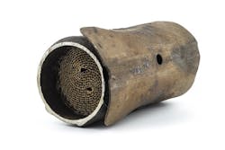
(Fig. 1) This Toyota had the catalytic converters stolen. When cut out, the coolant tube to the rear heater was cut causing loss of coolant. If not inspected and repaired, the vehicle could have overheated, possibly causing further damage.
CONTAMINATION
While contamination could come from many different fluids, chemicals or elements not intended to pass through a vehicle’s exhaust system, we will only look at the more common types of contamination:
Coolant
This could be from any gasket or other seals allowing coolant to leak into the combustion chamber or exhaust.
Oil
Any engine mechanical failure that allows excess oil to pass into the combustion chamber.
Silicone
While less likely today, the use of silicone in the exhaust system will cause contamination. Silicone typically has a maximum temperature of around 700 degrees. With exhaust systems reaching temperatures more than 1,200 degrees, the silicone will burn off fuel resulting in contamination of the catalyst.
Also, watch out for the use of Teflon on exhaust components such as O2 sensors. Excess or loose Teflon making its way to the catalytic converter will cause contamination.
Fuel
While this is a form of contamination, let’s look at this more in the thermal failure section.
THERMAL DAMAGE
In my experience, this is the most common cause of catalytic converter failure. Misfires, air-fuel ratio faults and exhaust leaks can all result in excessive hydrocarbons and/or oxygen in the exhaust resulting in extreme temperature. Here are some causes of thermal damage.
Engine misfires
Whether the misfire is caused by an ignition, air/fuel or mechanical fault, it will result in an increase of unburnt fuel and/or oxygen in the exhaust. This can result in increased temperatures in the catalytic converter.
Air/fuel calculation faults
Verify all sensors used for fuel injection calculation are performing properly. This includes MAF sensor, MAP sensor, O2 sensors, Coolant temperature sensor, TPMS and fuel pressure sensors.
Air intake control
Be sure to verify there are no vacuum leaks and IAC or throttle body operation and cleanliness.
Exhaust leaks
Exhaust leaks can result in an increase of oxygen in the cat, as well as an incorrect O2 sensor reading resulting in inaccurate fuel calculation.
EGR system faults
EGR systems are used in an effort to reduce NOx emissions output. To do this, the exhaust is recirculated into the combustion chamber. Because the exhaust lacks oxygen the combustion temperature is reduced making the creation of NOx far less efficient. If the EGR system is not functioning properly, the exhaust temperature may be higher.
This may seem like a long list of potential causes of failure, and it is. However, testing for these failures shouldn’t be too difficult in most situations. For the most part, we can verify the cause of failure is corrected with relatively few different tests.
Anytime you replace a catalytic converter, you should be inspecting the failed part in an attempt to determine the cause. We have pretty well outlined what to look for when physical damage has occurred. Let’s look at some tests that should be performed for specific failures. Then we will outline testing that should be performed anytime a catalytic converter is replaced.
CONTAMINATION FAILURES
Silicone or Teflon
Inspect the exhaust system and oxygen sensors for use of silicone or Teflon and remove if found.
If none is found in the exhaust system, be sure to inspect for improper engine repairs. Intake manifold gaskets and head gaskets are a good place to inspect for evidence of silicone usage.
Coolant
Be sure to perform a head gasket integrity test or combustion to cooling system leak test. There are several different methods of testing for these failures. Choose whichever you prefer.
Perform a cooling system pressure test at various pressures up to the cooling system cap maximum pressure specification. A leaking intake manifold or throttle body gasket may be difficult to find. Varying your testing pressure is a good method to help.
Oil
This will require engine health and crankcase ventilation testing. Start with quick and easy tests such as a relative compression test and measuring crankcase vacuum before moving to more in-depth testing.
A restricted air filter can cause oil to enter the intake system.
Turbocharger failure leading to oil consumption is more common with turbocharged engines becoming more popular.
Physical damage or catalyst that has substrate missing
An exhaust back pressure test should be performed to verify no other components of the exhaust system have been restricted. There are many ways to perform this test. My preferred method is using a lab scope with a pressure transducer installed in the spark plug hole. If you have not used this method before, there is a pretty steep learning curve. I would strongly suggest taking a training class or practicing before condemning a failed part.
Let’s look at how to measure back pressure with a mechanical gauge or pressure transducer connected to the exhaust system
You can purchase an exhaust pressure test kit. I chose to build my own. If you would like to as well, here are some instructions. First, you will need a pressure gauge (I used a gauge designed for welding gasses that reads from 0-30 psi), and install filings to allow connection to a rubber hose. Next, you need a method to connect the gauge. Always choose the easiest method. Here are a few choices in the order I prefer to use them:
Thread into the O2 sensor bung using an adapter.
To build your own, drill through the center of an 18mm x 1.5 flange head bolt (an oil drain plug works well), then tap the hole and install a barbed fitting allowing a connection to the gauge.
Connect the hose of the gauge to the DPFE sensor tubes on equipped vehicles.
Connect the hose of the gauge to the air diverter valves for the air injection on an equipped vehicle when possible (you will need to open the valves during testing).
Purchase or build a test probe. See picture for design. Materials needed:
1/8-inch copper tubing (commonly used for aftermarket or performance oil pressure gauges).
¼-inch brake tubing to install over the majority of the copper tubing for strength and a handle.
Welding wire bent to hold the probe in the exhaust pipe.
To use this adapter you will need to drill a 1/8-inch hole in the exhaust pipe. When testing is done the hole will need to be welded closed which is why this test is my last choice.
Once connected to the exhaust, start the engine and spike the throttle a few times. Typically a good exhaust system will not even bump the needle. You can see on my gauge I painted a red line starting at 5 psi. I believe a good rule of thumb is 0-3 psi no concern, 3-5 psi inspect further, 5+ psi needs to be addressed.
Keep in mind excessive back pressure can be anywhere in the exhaust system after the test location. If a restriction is found, you will need to move your test port down the system to find the cause.
For example: if a restriction is found at test point 1 and not at test point 2, the catalytic converter is restricted, and you will not need to test at point 3.
Thermal failure or cause not identified
Monitor fuel trims while in closed loop at idle, and on a test drive (record data to review when parked). Remember long- and short-term fuel trims combined should be within plus or minus 10%.
This is our best indicator of a fuel-air ratio problem. Remember if fuel trims are high or low, it does not mean the exhaust is rich or lean. If the feedback system (O2 sensors) is functioning properly, this means the exhaust would have been rich or lean had a fuel trim correction not been made. Regardless, the cause of the fuel trim correction still needs to be determined and repaired.
Verify the front and rear O2 sensor operation.
This can be quickly verified by causing a rich and lean condition while monitoring that the O2 sensor responds.
Another method is to monitor LAMBDA using a gas analyzer in the tailpipe. LAMBDA should be very close to 1.00.
A LAMBDA reading higher than 1.0 indicates excess oxygen or a lean condition.
A LAMBDA reading less than 1.0 indicates a lack of oxygen or rich condition.
You can determine a faulty oxygen sensor if Lambda is not near 1.0, and the percentage of fuel trim correction roughly matches the LAMBDA difference.
For example, if total fuel trim is 20% and LAMBDA measures near .80, this would indicate the oxygen sensor reported roughly 20% lean. The ECM added 20% fuel trim to compensate, yet the resulting exhaust is 20% rich.
Verify there are no exhaust leaks after the repair.
With the engine running, hold a rag against the tailpipe and listen for exhaust leaks. This is generally best tested when the exhaust system is cold.
Check when spark plugs are due for replacement and recommend replacement if due.
If no records are available, remove a spark plug for inspection.
Monitor Mode 6 data for any counted misfires. Perform further testing if found.
REFERENCE LIST
Here is a quick reference test list to follow any time a catalytic converter has been replaced after the cause of failure has been found and corrected, or after some baseline testing has been performed if no cause was determined.
Perform the test list in order
Monitor fuel trims, verify combined trims are within + or - 10%.
Reset KAM, ECM memory or clear codes even if none were stored.
Test drive vehicle.
Feel for a lack of power.
Listen for any abnormal noises such as:
Exhaust leaks.
Rattling.
Squealing/whistling.
Shut the ignition off then restart the engine.
Check for any stored or pending codes.
Verify fuel trims once more.
Check history records against spark plug replacement intervals and recommend if due.
When performed efficiently, this test plan shouldn’t take more than a few minutes on top of your post-repair test drive. Taking this extra time could prevent your customer from a return visit or a costly repeat failure. I have no doubt you understand the importance of finding the cause of failure for any repair you perform. The problem is many times we don’t understand what could or did cause the failure. We may even believe some of the parts we have replaced just have a service life that has been met. If you didn’t already, I hope you now understand catalytic converters should not fail if manufactured properly and installed on a properly operating vehicle.
About the Author

Jake Sorensen
Jake Sorensen is the 2019 NAPA ASE Technician of the Year and 2019 Ratchet + Wrench All-Star technician of the year. He is an ASE Master Technician with L1, L2 and L3 certifications. He is the shop manager and diagnostic technician at McNeil’s Auto Care in Sandy, Utah, where he developed the NAPA Auto Care national apprenticeship program.