We are all faced with no start issues from time to time. Some are of the basic and fundamental in nature while others on some late model vehicles can be somewhat complex. We will begin this article covering a no crank or no start condition. Most all late model vehicles are equipped with a theft deterrent system. The challenge is determining which systems lock out the starter.
For example, the early GM Pass Lock systems did not lock out the starter. The PCM would disable the injectors within two seconds of a startup. These systems were a favorite of car thieves who traveled in pairs. While one thief entered the car and knocked out the ignition switch the other thief was under the hood with a can of carburetor spray cleaner. As soon as thief No. 1 got the engine cranking thief No. 2 shot carb cleaner into the intake and the engine RPM exceeded 200 RPM. At that point the BCM (the dominant Pass Lock Module) saw the engine RPM above 200 RPM and assumed the fault occurred after a successful start and simply set a DTC for a Pass Lock failure and the thieves drove off with the vehicle.
Because of this the GM Pass Key 1 and Pass Key 2 systems and some other theft-deterrent systems will lock out the starter. Aside from the mechanical cut of the Pass Lock key, there are no electronics inside a Pass Lock key. On the GM Pass Key 1 system the ignition key has a resistor embedded in the key. The resistor element pulls a voltage value low. When this voltage value is recognized by the theft-deterrent module a signal is sent to the PCM which allows the PCM to ground side control the starter enable relay while the PCM allows for injector operation. The resistive elements embedded in the key are known to wear down which creates an open. When this occurs a no crank condition will exist. Whenever faced with a theft-deterrent issue it is always best to request both keys from the car owner. This rule should apply to all vehicle systems except the GM Pass Lock systems. Also keep in mind that some key transponders contain a battery that may be depleted.
We begin with a voltage test of the vehicle’s battery. Most technicians know that the battery is buried underneath the back seat on some vehicles. Notice in Fig.1 the battery ground is connected to body ground.
Let’s take a look at a starter system schematic from a late model Cadillac which experienced a no crank condition in Fig. 2. The number 1 DVOM in Fig. 2 showed good dynamic voltage from the ignition switch in the crank mode. Meter reading 2 went to 0.4 volts indicating the PCM was ground side controlling the pull in the windings of the starter enable relay. Now we look for good dynamic voltage from the power side of the starter enable relay in DVOM number 3 which also indicated good dynamic voltage. Now to meter reading 4 which is the main positive feed cable to the starter which also showed good dynamic voltage.
What you are not seeing here is the voltage drop from placing the positive meter lead to the block and the negative meter lead back to the battery negative terminal which indicated nearly full voltage from a bad negative ground cable from the block to body ground. Fig. 3 shows the bad ground cable. We were curious as to why we had a laundry list of U series codes from all modules on the class 2 circuit including the theft deterrent module. So we scoped out the class 2 signal at the DLC. In Fig. 4 note that the class 2 signal shifted well above ground when we went to the cranking mode. This initially told us that a bad ground existed. The block to body ground cable was replaced.
A late model Oldsmobile vehicle came in with a very intermittent stall and no crank conditions. After several test drives we finally got the car to stall. In Fig. 5 we probed the main feed pink wire coming from the ignition switch and with our meter in the Min/Max mode we caught the loss of voltage from a bad ignition switch.
Most technicians when faced with a no start will check for spark with a spark tester. When doing so it is important to know the KV value of different spark testers. Note Fig. 6. The spark tester on the right is known as a ST 115 meaning that it requires a 15KV to bridge the gap. This tester is used on the conventional breaker point ignition system. The ST125 shown on the left is used on the modern day high energy systems such as H.E.I. and COP systems. The adjustable spark tester in the rear of Fig. 6 can be adjusted to apply to all systems. A three-quarter-inch air gap will require about 30 KV.
I want to share a case study with you that illustrates the importance of knowing which spark tester to use. A high mileage 4.3L S-10 came in with a complaint of a good crank and a no start condition. Using the ST125 at the coil wire showed a good consistent spark. Using the ST125 at the end of a plug wire indicated no spark. The vehicle has all new secondary components. We then decided to use the ST 115 at the end of a plug wire which also indicated no spark. What could be the problem? We determined that a bad timing chain had created a bad alignment between the tip of the rotor and the distributor cap causing a loss of voltage inside the distributor cap.
I want to share with you one of my favorite tests in conducting the WOT cranking KV test. We are using the bar graph mode in Fig. 7 which is essentially the firing line. Notice the 29 to 30 KV values. This test does confirm three essential points — one being the ability of the ignition system to deliver 30KV. Second, it also stresses the insulation of the secondary circuit, and third, it verifies good compression values. COP wands are indicated in Fig. 8. These wands can be used on plug wires and COP units to check for a secondary event such as what is shown in Fig. 9. Notice the 10KV firing line and the two millisecond spark duration.
A Chevy Express van came in with an intermittent stall and no start with a crank sensor code. The crank sensor has been replaced twice as shown in Fig. 10.
Looking at the schematic in Fig. 11 we tapped into the CKP circuit. Look at the waveform in Fig. 12. You can see the signal drop out.
Fig. 13 indicates a must have tool with a low inductive amp probe. We know that there are several engines where the coils are buried under the valve cover making it very difficult to check for spark. Using the low inductive amp probe and clamping the probe around the B+ feed wire an amperage waveform will verify that we have proper coil saturation as in Fig. 14.
Low inductive current probes are very valuable in checking for mechanical, electrical and fuel pressure.
Notice Fig. 15 where we simply removed the fuel pump fuse and jumpered across the jumper lead with our amp probe. Fig. 16 and Fig. 17 verify the importance of mastering the low inductive amp probe.
Fig. 18 specifically addresses some common failures on the Hyundai and Kia systems where the PCM needs to see a crank start up to give the injectors more enrichment during start up. In addition the main relays are known to fail causing a no start. Fig. 19 shows the schematic.
Fig. 20 shows the main relay schematic. Notice that the main relay powers up the PCM and the injectors. A very intermittent no start came in on a Kia. A scope was set up to monitor the main relay in and power out as well as the B+ to the fuel pump. Fig. 21 shows the failure. Notice power into the main relay is there but no power out. You can also see that there is no B+ to the fuel pump. Fig. 22 shows good voltage out of the main relay and B+ to the fuel pump.
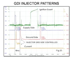
Checking for injector pulses on GDI engines will require a DSO. Fig. 23 shows the voltage trace and the current flow values on a GDI engine. If checking for a voltage trace you must use two channels of the DSO. When using a current probe we simply clamp around one injector wire.
Back in the old days a spark tester and a can of carb spray cleaner was all that was needed to check for loss of spark or fuel pressure. On today’s modern engines the amp probe becomes a tool of necessity.
The industry is better because of your commitment.
About the Author