Data communications have matured tremendously in the 40 years they’ve been around. Today, it’s not uncommon to find automobiles fitted with multiple networks using different communication standards. For diagnosticians armed with the right knowledge and tools; most network communication challenges can be resolved. Most of us deal with networks daily and rarely need to go to the signal level. For the most part, scan tools do all the heavy lifting for us by bringing us the data in a readable and organized fashion.
Basics
Serial data in its simplest form can be described as a party line where everyone connected can listen for important information. There may be times where a listener needs to talk, and this is where a communication protocol comes in. A single wire network is usually suited for low speed, non-mission-critical data such as a Local Interconnected Network (LIN). Using a LIN is an attractive solution due to its overall low cost. So, if the OEM can reliably provide communications and meet their objectives, LIN will likely be used. For really important, timely information, other network busses that support higher speeds will be used.
High-speed CAN
Today’s two-wire version is an evolution from the original designed by BOSCH back in the early 1980s. Today’s form is a result of years of industry collaboration by various workgroups. Soon, we’ll likely see new network protocols due to the amount of data needed to support new vehicle technology. Today’s most popular is High-speed CAN. It’s designed to carry balanced signals over a pair of twisted wires connecting multiple modules. Binary data is broadcast across the network.
For both LIN and CAN, each payload message within a CAN frame is limited to a maximum of 8 bytes (64 bits) (Figure 1). As vehicles and technology continue to intersect, this presents major challenges.
Since the circuit under test is a parallel circuit created by two 120 ohm terminating resistors, a normal reading should be around 60 ohms. If it’s not, you’ll need to pare down the network and isolate. Keep in mind that if you have an intermittent problem, you can try performing wiggle tests on circuit connections while monitoring your DVOM. In most cases, the scan tool, DVOM, and wiring diagram should provide everything needed to address network challenges. There are other tools still that might also provide additional assistance. If you work on GM vehicles, the Data Bus Diagnostic Tool (Figure 2) application from General Motors can be useful, as it provides a deeper level of network intelligence.
The oscilloscope is another useful tool, but you’ll want to make sure the scope you choose is fast enough to sample and acquire data for bit level analysis. If your scope isn’t fast enough, you can still make a few useful observations. One would be to ensure that both CAN-Hi and CAN-Low mirror each other (Figure 3).
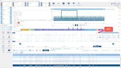
Picoscope also provides serial decoding tools that might prove to be helpful as shown in the case study below.
Case Study
A 2014 Corvette came in for a wheel alignment. As part of the post alignment process, the SAS (steering angle sensor) required a reset/relearn. As soon as we performed the reset, warning lights appeared on the dash. The PSCM reported U0428 as current. A U0428 indicates that the PSCM has received invalid data from the steering wheel angle sensor. With the scan tool monitoring PSCM data, the SAS always reported zero. When we logged into the EBCM, SAS reported approximately 187 degrees with the wheels pointed straight ahead and would change linearly as the wheel was turned in either direction.
At this point, I was baffled as to why the steering angle sensor failed. After reviewing service information, the wiring diagram quickly revealed that this sensor was on the GM High-speed CAN expansion bus with access available at pins 12 and 13 of the DLC (Figure 4).
It was certainly looking like there was something wrong with the steering angle sensor, but I wanted to know more, and I knew who might be able to help me. I reached out to Dmitriy Levchenkov who I met on Diagnostic Network – diag.net. Dmitriy holds a PhD in operations research and industrial engineering, as well as a master’s degree in computer science, both from Cornell University. I started a discussion on DN and provided him with a short recording of the expansion bus from the broken vehicle along with the same data from a similar vehicle. He was able to take a look at the data and identify that message ID (1 E5) was where the SAS reports on. He was then able to determine that bytes 2 and 3 are used to report the angular position and byte 1 was likely reporting sensor status although we were never able to find a data sheet on the sensor.
After we replaced the defective sensor, byte 1 HEX changed from 1C (Figure 5) to 5C (Figure 6). If you’re interested in seeing more, look for the reference link in the side bar.
Going Deep
There are other tools out there that let you explore vehicle networks. Some software applications can assist with deciphering network messages. (Figure 7) Learning more about said software can help to de-mystify its inner workings and let you gain a deeper understanding and appreciation for vehicle networks.


