Vehicles affected:
- 2004 Dodge Ram 5.9L Diesel
- 2006 Ford F-150 5.4L
- 2007 Jeep Commander
Tools used:
- Scan tool with Mode $06
- Vehicle repair information
- Aerosol keyboard cleaner
- Heat gun
- DMM
- Power Probe IV
- High-pressure leak detection smoke machine
Why should you be interested in an article on emission diagnosis and repair if you don’t test emissions? Because you diagnose and repair vehicles equipped with OBD-II.
OBD-II was created with a few purposes in mind; to test both the electrical and functional capabilities of a vehicle’s engine control systems to assure they are meeting emission standards, alert the driver if there is an issue and standardize vehicle communication to diagnostic tools. Since you work on vehicles equipped with OBD-II, understanding the design and functions of its components will assist you in both turning and keeping that pesky “check engine” light off.
A check engine light that is illuminated means that one or more of the emission components is not functioning properly, resulting in the vehicle exceeding the Federal Test Procedure emission limit by 1.5 times. An illuminated “check engine” light also means you will be able to obtain some information directly from the vehicle’s computer system as to what component or system is not working properly.
An additional benefit of OBD-II mandates was the DLC, or Data Link Connector, would be universal and placed in generally the same area of the dash on all vehicles. This also allowed for scan tool manufacturers to communicate with all vehicles in a common manner.
Scanning the vehicle will provide you with fault codes, indicating which part of the system is not meeting standards. Obtaining freeze frame data will provide information as to what the vehicle operating conditions were at the time of the code setting. This information is helpful not only to recreate the condition while diagnosing the issue, but to verify the system is functioning correctly after the repair.
One capability and function of your scan tool that is under-utilized and misunderstood is Mode $06. Using Mode $06 on your scan tool allows you to examine the test results of various monitored systems to see if they are passing or failing. Passing a test means the system is working within limits and a resulting “complete - pass” would be displayed on that particular monitor result. Failing a monitor test means the monitored system has an issue and the vehicle may exceed emission standards and results in a “complete - fail” result will be displayed and the “check engine” light will illuminate.
A frustration many technicians have is when monitors have not “run” or they do not complete. Running a monitor means that the vehicle must operate under strict conditions in order to test that specific system. An incomplete monitor means that the vehicle has not met one or more of the conditions required to test the components in that particular system.
We will look at a couple of vehicles to see what caused their monitors to not run.
Issue 1 - Failed emissions due to the “Comprehensive Component Monitor” not completing
Vehicle: 2004 Dodge Ram Pickup with a 5.9L diesel
Tools used:
- TSBs - Mitchell 1
- Scan tool
- Aerosol keyboard cleaner
- Heat gun
- DMM
Step 1: Scan the vehicle
Scan results indicated no codes were present and none of the monitors had been completed.
Step 2: Obtain vehicle information
It is a good idea to begin searching for information with a check for relevant Technical Service Bulletins (TSBs). TSBs are generated when the vehicle manufacturer has been made aware of issues consistent with a specific vehicle platform or engine control system and have a common cause as well as a common repair. TSB fixes can consist of replacing components, changing PCM programming, or both.
We were able to find a TSB relating to a powertrain control module (PCM) programming change directly related to the vehicle not completing the Comprehensive Component Monitor in our Mitchell 1 ProDemand database.
At first look it seemed a simple programming change would fix the vehicle. Additional information within the TSB directed us to check the current software version installed. Checking the serial number confirmed the vehicle already had the latest software version installed and the TSB would no longer apply.
The next step in the information process is to determine what the vehicle required to perform a drive cycle. A drive cycle is a series of self-tests performed under conditions spelled out by the vehicle manufacturer that will allow each monitored component and system to evaluate its ability to work properly.
In this, as well as most vehicles, it is necessary for the PCM to perform a “cold start.” To determine if the engine looks at the data from the Engine Coolant Temperature sensor and the Ambient Air Temperature (outside air) sensor to determine if they are within 10 degrees F of each other. Most vehicles use the intake air temp sensor to communicate the outside air temperature to the PCM. This vehicle, being a diesel, actually has a separate ambient sensor as well as an intake air sensor.
Step 3: Perform diagnostic tests
Observing the scan data we found the ambient air temperature sensor was stuck at 110 degrees F. Since the engine was cold and it matched the outside air temperature of 62 degrees F, we suspected the air temp sensor was not allowing the PCM to ever determine the engine was starting “cold.”
We scanned the PID for the ambient air temperature PID while we both cooled and heated the sensor. Using a can of aerosol keyboard cleaner we sprayed the sensor in order to cool it. Even though the sensor frosted over, the PID value showed 110 degrees F. We then used a heat gun to warm the sensor and it still showed a 110 degree F temperature.
To verify the sensor was the issue and not the PCM or wiring, we repeated both tests using a DMM to check the sensor’s resistance value. In both the “cold” and “hot” tests, the resistance of the sensor remained at 4k Ω (4,000 ohms).
Step 4: The repair
We replaced the ambient air temp sensor, then rechecked with the scan tool to see if the PID value matched the outside air. Since it did, we drove the vehicle to see if the monitors would run. Since the PCM was now able to determine the engine performed a cold start, it was able to run and complete the monitors.
Issue 2 - Always displays a P1000 code
Vehicle: 2006 F-150 5.4L
Tools used:
- Scan tool
- TSBs - Mitchell 1
- Power Probe IV
Ford vehicles will set a P1000 code if monitors have not completed. Normally Fords will run monitors very quickly, but this one seemed like it would never run any monitor. After clearing codes, a P1000 also will set because the monitor status is reset as well as any fault codes.
Step 1: Scan the vehicle
We decided to drive the vehicle and check the monitor status prior to turning the engine off. When we did this our scan tool showed all of the monitors had completed except the EVAP system monitor, which is normal for most vehicles as the EVAP system can take a few trips to complete.
Step 2: Obtain information
We checked for TSBs and found none pertaining to this issue. Since we had determined the vehicle would perform its monitor tests with the engine running but they cleared when the key was off, we suspected the keep-alive power to the PCM had an issue. Looking at the wiring diagram showed the keep-alive circuit to the PCM was powered by fuse #5 in the underhood junction box. Using a Power Probe IV we found we had power on both sides of the fuse when the engine was running but not when the engine was off. We had power with the engine running because the circuit would feed back to the #5 fuse from the PCM relay with the engine running.
Step 3: The repair
We were able to trace a broken wire in the harness that supplied battery power to the fuse. Once power was restored the vehicle was capable of completing and saving the results of its monitor tests.
Issue 3 - Ongoing issue with a P013C fault code and history of P0430 code
Vehicle: 2007 Jeep Commander 5.7L
Tools used:
- Scan tool
- Repair information - Identifix
- High-pressure smoke machine
The last vehicle we will look at has had an ongoing issue with a P013C fault code and history of a P0430 code. P0430 is a catalyst efficiency code, P013C indicates a slow response from rich to lean on the bank 2 rear oxygen sensor.
Step 1: Scan the vehicle
We scanned the Jeep and found a current P013C code. Freeze frame data did not provide any helpful information, and the sensor seemed to be working normally at this time.
Step 2: Obtain information
We discussed the issue history with the vehicle owner. The oxygen sensor had been replaced and a flash program update specific to this issue had been performed only to have the code return. Since we did not have much information to go on from freeze frame data and the system seemed to be operating normally now, we chose to look at IdentiFix Direct-Hit to see if there were any similar repairs listed.
There were some reports of similar issues with the same code being caused by exhaust leaks. The customer stated he had the vehicle tested at an exhaust shop and they found nothing leaking by using a stethoscope to listen for leaks. The problem with trying to use a stethoscope to listen for an exhaust leak is as soon as the engine starts there is enough heat to quiet the leak due to metals expanding and sealing it up. Even though the leak is sealed enough to be quiet, the slightest amount of air entering the exhaust system can alter what the oxygen sensor reads. Pulsations in the exhaust stream from normal engine operation can actually draw extra air into the exhaust. When this air is in between the front and rear sensors it will look as if the catalytic converter is not working correctly, which could explain either code.
Step 3: Perform tests
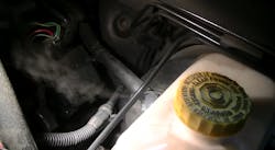
Unwanted or unmetered air can affect both upstream and downstream oxygen sensors. Smoke testing the intake and exhaust systems is one way to determine if any issues are present. Smoke testing the intake system to find any vacuum leaks found an unknown and undetected leak at the brake booster check valve.
To test this vehicle, we used a Redline Detection high-pressure smoke tester. Regular smoke testing can be invaluable for checking vacuum leaks and EVAP systems, but the high-pressure/high-volume tester allows testing of higher-pressure systems like turbo and exhaust systems.
When the high-pressure tester was installed in the tailpipe, a very visible leak showed up at the weld in the “Y” pipe in front of the catalytic converter.
Step 4: Repair the vehicle
The “Y” pipe was replaced as well as the brake booster check valve. At this time the fault code has not returned and there was an added benefit - a slight increase in fuel economy from the previously undetected vacuum leak at the brake booster.


