This article was originally published February 4, 2016. Some of the information may no longer be relevant, so please use it at your discretion.
Vehicle: 2011 Cadillac SRX
Symptom: Air conditioning system does not cool
Tools used:
- Service Information
- RRR (Recover/Recycle/Recharge) machine with vacuum test capabilities
- Electronic leak detector
- UV dye kit
- Bullseye Leak Detector
This vehicle was brought in with an air conditioning system that was not cooling properly. The initial inspection showed that the compressor was not operating.
Step 1: Confirm basic operating conditions are present
The basic components for compressor operation are:
- Mechanical (the compressor)
- Electrical (power to the compressor)
- Pressure (amount of refrigerant)
This vehicle, like most late-model vehicles, utilizes the BCM (Body Control Module) and PCM (Powertrain Control Module) to supply power to the A/C compressor. The control modules look for a request from the switch, as well as various temperature sensors and inputs from other sensors to make sure the pressures within the system meet certain requirements in order to activate the compressor. This is done in part to make sure damage to the A/C system will not occur if oil is not flowing through the system. Oil flows through the system via the refrigerant, so if the refrigerant is low, essential lubrication cannot occur.
Due to the system requirement of needing pressures within specifications to operate the electrical portion, and the electrical portion necessary to operate the mechanical part of the system; the quickest way to start the diagnostic process is to check system pressures first.
This vehicle’s A/C system uses R-134a refrigerant. We installed the RRR machine and determined there was no pressure in either the high or low side indicating there was no refrigerant in the system. Because the system was empty, it was fairly obvious there was a leak in the system. This vehicle was delivered to the shop in early spring, which may not seem important, but knowing how long it has been since the A/C worked properly can give a clue to how large the leak may be. Discussions with the client revealed the system did not seem to be cooling as well late last summer, which likely means there was a leak for well over six months.
Step 2: Obtain information
Obtaining system specifications is necessary in order to charge the system to the correct amount of refrigerant, as well as to check for any relevant service bulletins. Using ALLDATA service information, we found no relevant service bulletins. We also determined the system holds 1.6 lbs of refrigerant. This is important in order to charge the system correctly, but also can give you an idea of how large the leak could be.
In some of today’s vehicles, the amount of refrigerant can be less than 1 lb (16 oz). On a small system like that, it could be a small leak that could cause the system to not operate. On larger systems, it could either take a longer period of time to affect operation, or need to be a larger leak to cause an issue.
There are essentially two types of leaks that can occur in an A/C system:
- An active leak, meaning that the leak will occur at all times and can, in many cases, be detected fairly easy.
- A passive leak can occur intermittently and only under certain conditions such as temperature, pressure, vibration or torque.
Determining how to find the leak and which tools to use are dictated by the type of leak.
Step 3: Vacuum test the system and charge the system
No matter which type of leak there is, you need to start by evacuating any remaining refrigerant and drawing a vacuum on the system. A requirement for modern RRR machines is to have vacuum test ability. The machine must be able to reclaim the refrigerant and draw and maintain a minimum of 29” of vacuum.
Vacuum is necessary to make sure any moisture is removed from the system prior to charging with new refrigerant. Vacuum testing is also done to determine if there are leaks in the system prior to charging.
There are issues with relying on vacuum testing to determine if there is a leak:
- When your hoses are installed in the system, the service ports are sealed, which may indicate the component that is leaking.
- In some cases, such as a pinhole in one of the hoses, a vacuum can cause the leak to seal and maintain a vacuum. Partly due to vacuum testing not being 100 percent reliable, California’s Bureau of Auto Repair requires leak testing at a minimum of 50 psi.
- Even if you determine the system will not maintain a vacuum, it does not indicate where the leak is and additional leak test methods will be required. Charge the system to its full capacity if the vacuum leak test passes.
Step 4: Use an electronic leak detector
Active leaks most likely will be found using an electronic leak detector. If you have been in the auto repair industry since the R-12 refrigerant days, you probably have trouble relying on an electronic leak detector. The detectors available at that time were reliable only if there was a major leak. They were also known for reporting leaks when there was not one present, due to both the characteristics of R-12, and the presence of other chemicals under the hood.
The current version of the detectors are worth the investment for many reasons:
- The newer tools are required to meet SAE standards for their ability to detect leaks in incredibly small amounts, (0.25 oz per year).
- R-134a and R-1234yf are much different in their chemical makeup than other chemicals and fluids under the hood, and newer detectors are less likely to report a false positive result.
We used our Matco ACRX1 leak detector and checked the normal areas for active leaks, such as the compressor housing and seals, connections, service ports, and condenser seams. There were no leaks found with the detector, or from a visual inspection looking for refrigerant oil residue that has collected dust.
Even though the electronic detector has the ability to report very small leaks, it may be difficult to locate them due to environmental factors. Here are a few helpful tips to assist in finding leaks when you are working in the shop:
- Control your environment (close the shop doors to reduce air movement in the shop).
- Turn off the engine (primarily for safety reasons but also to reduce air moving under the hood).
- If you suspect a compressor leak, place a shower cap around the compressor and insert the leak detector tip inside the shower cap.
- Prior to testing, use shop air to clean dirt and grime from the compressor, condenser and hoses.
- Ensure the tool’s batteries are good, and the tip is clean.


Step 5: Install leak detection dye
Since we were unable to locate the leak with our electronic leak detector and had determined that this leak had been happening for some time, our approach switched to locating a passive leak.
Since passive leaks are intermittent or only present under certain conditions, look for things that may not be obvious during a normal A/C service. Some things we have found in the past were hoses that were misaligned and bent when the hood was shut, causing a leak and broken motor mounts that pulled on a hose when the motor torqued up on acceleration.
One of the easiest ways to check for a passive leak is to use a UV (ultraviolet) dye kit to insert a fluorescent dye into the system. When the conditions are present to create the leak, the dye will leave a stain showing where the leak is. You also should keep in mind leaks can occur in places that are not easily seen and using dye can assist in finding leaks by leaving a trail leading to the origin of the leak.
When using dye, make sure that you follow the instructions regarding how much dye to insert into the system, and that the dye is correct for the type of refrigerant. Using too much dye can over-charge the amount of oil into the system, and using the incorrect type of dye can cause compatibility issues with the oil and/or refrigerant in the system.
In most cases, having the customer drive the vehicle while using the A/C for a few days, or even a few weeks, will allow the dye to flow throughout the system and indicate the location of the leak. When looking for the leak, use a UV black or blue light, and tinted glasses, to look for dye traces. In some cases, turning the lights off or closing the shop door to darken the bay will assist in seeing the dye.
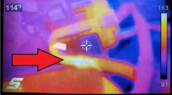
We released the vehicle to the customer and had them return after a week of driving. Upon its return, using the UV glasses and light we were able to see traces of dye on the frame under the liquid line tubing from the condenser to the evaporator. The leak was coming from a part of the tube that was hidden by insulation over the tubing.

Step 6: Repair and charge the system
Install the RRR machine to recover any refrigerant and oil from the system. Using an assortment of hand tools, we replaced the liquid line and, as we always do, replaced the accumulator and service port O-rings. We do this to assure that there is no moisture in the system and reduce the possibility of future leaks in the service ports.
Remember during the installation process to use only mineral oil, not PAG oil, on all the fittings and O-rings. This helps to prevent thread galling or damage.
Using the RRR machine, draw a vacuum of 29” and maintain it for at least 20 minutes. Install the same amount of oil removed from the system during the recovery process and add additional oil for any components that were replaced such as the accumulator.
Then, charge the system to the manufacturer’s specifications and disconnect the machine. It is okay to leave any residual dye in the system as it is compatible with the system and may help find leaks in the future if they occur.
Finally, make sure to re-install the service port caps as they will prevent contaminants from entering the system.