.")
Vehicle Effected: 2010 Dodge Caravan
Issue: A/C inoperative, blows warm air.
Tools Used:
- Vehicle information
- Bi-directional scan tool
- Power Probe III
- Digital multimeter/clamp meter
- Refrigerant identifier
- A/C RRR machine
- A/C service port valve tool
- Electronic Specialties Fuse Buddy
- Temperature gauge
- Temperature probe
- A/C pressure gauge set
- J2534 Programmer
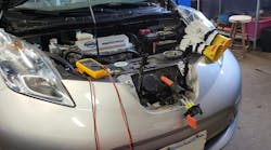
In this month’s tool briefing we will look at a 2010 Dodge Caravan that came to the shop with an A/C system that was blowing warm air.
Step 1: Gather information and pull codes
The first step in all diagnostic procedures is to gathering information. This information not only is obtaining system diagrams, specifications, component locators and TSBs from reliable vehicle information sources, but all of the information available from the customer.
The main reason for this is in order for the technician to start their diagnostic process he or she needs to verify the complaint. If an issue is intermittent, information from the customer will allow the technician to duplicate the conditions that initiates the failure. Once the technician has duplicated the customer’s concern they will be able to determine which system(s) may be the potential causes of the issue.
Our Caravan had an issue with the air conditioning system blowing warm air under all conditions. The potential causes of this could be a problem with the air conditioning system, a problem within the Body Control Module, engine overheating, or a blend door operating incorrectly.
One of the first observations was the compressor was not operating. Looking at the system diagram in Mitchell 1, the PCM controls compressor operation based on various inputs from sensors inside the vehicle as well as engine sensors.
Since the PCM controls compressor operation we used our scan tool to check for fault codes. We used the Delphi Scan Tool, but most aftermarket scan tools will provide this information, even in generic rather than enhanced mode. There was a code U0141 for a loss of communication with the TIPM (Totally Integrated Power Module).
Communication loss with any module on CAN vehicles should be checked first and a scan tool is one of the most useful tools to do so. Being that it can provide a DataStream as well as allow the technician the ability to operate some components by sending a command through the scan tool to the various modules (bi-directional), the scan tool should be one of the first pieces of equipment used.
This vehicle has a PID (Parameter Identification) value for A/C pressure as well as one for the compressor signal being on or off. Our scan reading showed the pressure was 487 psi. According to Mitchell 1, the compressor should operate at this pressure. The PID for compressor command was "on."
STEP 2: Test the system
The next step is to test the system to see why the compressor was commanded “on” but was not operating. Using the Power Probe III, we tested the A/C compressor fuse and found it was good.
We then tested the connector at the compressor clutch for power and it showed no power at the connector. Using the Power Probe III, we applied power to the connector and the circuit breaker built into the Power Probe tripped which indicates a short in the circuit. Since we determined that a short existed, disconnecting the connector at the compressor and using the Power Probe to test the circuit again will show if the circuit from the compressor connector to the vehicle has the issue, of if the compressor itself was the cause.
We found when we applied power to the compressor clutch, the breaker tripped again which indicated a shorted clutch coil. To verify this, we connected a DMM set on Ohms to the clutch and found no resistance in the circuit which confirmed the short. Since we observed on the scan tool that the compressor was being commanded “on,” we checked for power at the connector with the clutch disconnected and found power was present.
Step 3: Replace the compressor clutch
There can be reasons a clutch shorts out. Simply a faulty clutch could cause it, but a compressor that is binding or taking more power to operate can cause the clutch to work harder and eventually cause a failure. Contamination of the incorrect refrigerant and over-charging may also cause failures.
We know we need to replace the clutch, but we want a long-lasting repair so we need to determine the cause of the failure.
We started by using the refrigerant identifier to make sure there was no contamination in the system. The readings verified no contaminants so the next step is to evacuate the system to see if the amount of refrigerant matched the charge specification. We evacuated the correct amount so that indicated there was not an over charge that caused the clutch failure.
The next thing to check is to turn the compressor to check for binding, especially when first turning the compressor. Use the appropriate socket and a 1/4" drive ratchet to turn the compressor. This will allow the technician to “feel” the compressor resistance easier than with a larger size ratchet and socket.
The steps taken, checking for contamination, the amount of refrigerant, and compressor resistance should be performed in the order given to save time. Using the identifier first is necessary to make sure that if there is contamination, it does not enter your evacuation equipment.
Evacuating the system next will allow you to test the compressor without any resistance from pressure in the system. In order to assure a complete repair it is a good idea to fully evacuate and charge the A/C system prior to delivering the vehicle to the customer, even if there is a repair that does not require recharging the A/C system.
In this Caravan, there was very little resistance when rotating the compressor. Combined with the mileage on the odometer (31,500 miles) we determined the clutch could be replaced without replacing the compressor.
After installing the clutch, we used our Matco charging station to add the correct amount of oil (the amount removed from the system) and the correct amount of refrigerant. We also have been in the habit of replacing Schrader valves and caps in all service ports when working on air conditioning systems to prevent leaks and therefore comebacks. Use the appropriate valve tool or socket to replace the service port components.
Step 4: Test the system to assure a complete repair
In most cases this repair would be complete. In this case though, because of the design of the system, when the compressor clutch shorted, there were additional repairs necessary.
Once we assumed the repair was complete, we started the vehicle and turned the A/C on. Based on our earlier tests we expected the compressor to function properly after the clutch was replaced as we had power at the clutch connector when the scan tool commanded the compressor on. What we found was the clutch did not operate. One assumption could be that we had a defective clutch coil, another could be that there was an issue with the connector.
We used the Power Probe to supply power to the clutch and it engaged normally. Since it did, it confirmed that the issue was not due to a defective component. Using the Power Probe again we found the there was no power at the connector when the scan tool commanded it. We disconnected the connector and checked for power again and found that with it disconnected we showed voltage when the PCM commanded it, but we lost it when we connected the clutch. Our suspicion was that there was resistance somewhere in the circuit and it was not allowing enough current to flow to the compressor clutch.
Using the DMM again, we performed a voltage drop at the connector with it commanded on. Our voltage drop reading at the connector showed 10V, meaning that there was so much resistance in the circuit that it was only capable of delivering 10V less than system voltage (around 4V; system voltage of 14V less 10V of resistance).
Step 5: Replace the module
Going back to the circuit diagram we determined that the A/C fuse delivered power to the A/C relay and the PCM would energize the relay for compressor operation. Checking for the relay, we found that the relay was integrated into the TIPM.
Remember the U-code for loss of communication in the TIPM? We located the wire from the TIPM to the compressor and found no resistance in it. The next step was to check the relay itself but found that the relay was not a replaceable component and it would be necessary to replace the entire module. If you are not familiar with the TIPM, it is the entire fuse and relay box under the hood on this Dodge. Since this module is part of the CAN communication bus and is the “Gateway” module that carries all low-speed communication, it likely will need to be programmed upon replacement in order to “introduce” it to the network of modules as the new path of communication.
After replacing the module and using our J2534 programmer to provide both VIN and mileage information to the module, we started the vehicle and had the A/C system working normally.
Performing additional verification tests will make sure that the repair is complete. These tests include:
- Using a fuse buddy placed into the A/C fuse to make sure that the amperage to the compressor was within specifications.
- Use A/C pressure gauges to make sure pressures are within specifications.
- Use thermometer in the center vent to verify outlet temperature is correct.
- Use a temperature probe and your DMM on the evaporator inlet and outlet to make sure that there is at least a 50 degree F drop in temperature
All of these tests will assure that the system is operating normally and you have made an effective repair as well as the correct charge in the system.