Content brought to you by Motor Age. To subscribe, click here.
Welcome back to another edition of “The data doesn’t lie,” a regular feature in which I pose a puzzling case study, followed by the answers to the previous issue’s puzzle.
What You Will Learn:
• Although reliable for gross compression losses, a relative compression test may fail to reveal a slight leak
• Scan data should be viewed first to establish where to spend precious diagnostic time while on the hunt from driveability faults
• Ignition waveform analysis offers a view of the combustion process as it occurs... and without any disassembly
My good friend, Rick, was faced with a challenging 2017 5.4L Ford F-150. The truck exhibited a single-cylinder misfire that only reared its ugly head at throttle tip-in during the 1-2 gear shift. It never occurred under heavy load. Through experimentation, Rick could replicate the symptom in the work bay. In “park” and at 1,700 rpm, he could occasionally reproduce the misfire, giving him the opportunity to view some basic scan tool data. The data showed the misfiring cylinder to be cylinder #1.
Preliminary data
A fan of an easy and fast approach (considering the elusive fault) Rick thought it was best to swap both the fuel injector and ignition coil for cylinder #1 with those of a non-suspect cylinder. Reanalyzing the scan data after the swap of each component individually revealed the misfire remained with cylinder #1. This led Rick to go with his gut feeling about the fault being a mechanical one.
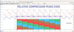
Using his Pico scope and amp probe, Rick proceeded with a relative compression test, on Channel A (shown as the blue trace in Figure 1). The result of the test didn’t readily display an obvious mechanical fault relating to a compression loss for cylinder #1, or any cylinder for that matter. This was the point where Rick reached out for my input.
After hearing what experiments had already been performed, I had a few important questions for Rick, as I was on the road and couldn’t perform my own research at the time. The first piece of data I requested was the underhood Vehicle Emission Control Information (VECI) label. The information on this label let me know if the engine had an EGR valve and what type of heated exhaust gas oxygen sensors (HEGOs) were utilized. Considering the fault was present at 1,700 rpm, I suspected a density misfire in which the introduction of EGR may disrupt the combustion process.
Just the facts, please
Because this vehicle does not rely on an EGR valve, it uses valve overlap to accomplish the same goal. It achieves this with variable valve timing (VVT). I asked John to view the desired and actual camshaft position PIDs, because I was interested in any error that may have been occurring. The results showed the desired and actual camshaft positions to match, indicating no existing VVT faults. I then asked John for the total fuel trim for each bank at the time of the misfire.
Bank 1= -13 percent
Bank 2= -7 percent
Although the two values deviated from each other a bit, this finding didn’t offer a “home run”. But the fuel trim values do offer a clue that we were not dealing with a fuel- or ignition-based misfire, leading us closer to a cylinder #1 mechanical fault.
The next logical test I suggested, due to the ease of access, was an analysis of an ignition capture at idle. Although the fault wasn’t present at idle, the ignition waveform reports the conditions within the combustion chamber at the time of spark discharge. If there was any type of cylinder leakage, we would surely see it here.
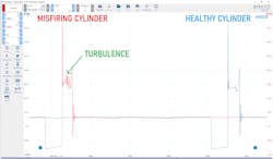
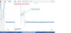
The results of the test were evident. The variation in conductivity within the combustion chamber was present. The horizontal line, known as the burn line, should be relatively flat at idle, representing little variation in conductivity. That indicates a dense air/fuel charge and a cylinder that can harness its contents properly. The one obtained from cylinder #1 (misfiring cylinder) was not flat (Figure 2). Keep in mind, the capture was taken without a misfire occurring, which worsened under elevated rpm (Figure 3 and 4).
The data doesn’t lie
With all the information in front of us, we are faced with deciding how to proceed. Here are some bullet points of what we know to be factual, and I will ask all of you, diligent readers, for your input:
- Vehicle misfires only under light load conditions
- Relative compression testing reveals no significant loss from the misfiring cylinder
- Fuel trim doesn’t indicate a bank-to-bank trim issue for a single-cylinder misfire
- Ignition analysis for the suspect cylinder reveals a variation in conductivity
Given this information, what would you do next?
- Replace spark plug for cylinder #1
- Perform induction cleaning service
- Clean VVT oil control valve #1
- Perform cranking pressure waveform analysis on intake and/or exhaust system
SOLVED: (July 2023, Motor Age) 2019 Honda Fit, P0172- rich condition
What would you recommend doing next, given the data bullet points in last month’s challenge?
- Replace skewed primary WRAF sensor
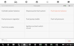
- Perform available direct injector automated scan tool test
- Replace all four direct injectors
- Replace skewed-high fuel rail pressure sensor
For those of you who chose answer #2, congratulations (Figure 5). Although the replacement of the direct fuel injectors was required (due to imbalanced fuel delivery), replacing the injectors without first testing them may have been proven to be a costly mistake. Like any electrical device, the direct injectors require healthy circuitry and injector-driver control to deliver fuel appropriately. So, choosing answer #3 is not the most appropriate answer.
Answer #1 is incorrect. Although a skewed primary WRAF sensor could indeed shift fuel trim negatively, the rear HO2S was similarly reporting a rich condition, indicating that the primary sensor was likely reporting correctly.
Answer #4 is not correct. If the fuel rail pressure sensor was skewed high, less actual pressure would be created and the direct injectors would underdeliver fuel. This would result in a lean condition, elevated fuel trims and possibly even a lean DTC. The most appropriate answer is answer #2.
Be sure to read next month's Motor Age issue for the answer to this month’s challenge and what was discovered!


