Content brought to you by Motor Age. To subscribe, click here.
What You Will Learn:
• A misfire is simply a lack of contribution to the crankshaft's rotation
• Misfire detection strategies can vary between vehicles
• Viewing the same data that the ECU uses to detect misfires can yield a diagnosis without relying on DTCs
We have all likely been there before. Faced with a vehicle exhibiting what the Engine Controller believes is a misfire. Some of us were lucky to realize that the ECU had misunderstood before the parts-cannon was fired too many times.
Troubleshooting the root cause of misfires should be an easy task, considering most gasoline internal combustion engines require only three factors to carry out a successful combustion event:
- Adequate ignition discharge (and at the proper time)
- Proper Air/Fuel ratio
- Cylinder mechanical integrity (compression and breathability)
So, why is it so many techs struggle to solve the problem? Or worse, why are so many parts being replaced unnecessarily? The answer likely lies with a lack of understanding of how the misfire is detected in the vehicle they are addressing.
The flavors of misfires
Contrary to popular belief, a misfire is not necessarily a cylinder lacking a combustion event. True, a lacking combustion event does indeed cause a misfire, but it is the slowing of the crankshaft that is the definition of a misfire
Anytime a cylinder fires and combustion take place, the nitrogen inside the air charge is heated by the combustion event. The heat causes the nitrogen gas to expand, and the pressure exhibited on top of the piston helps to propel it down and causes the crankshaft rotational velocity to increase.
If there is a lack of adequate fuel supply, a combustion event will either cease to occur, or it will not be as intense of an event as intended. Both possible scenarios will cause a slowing of the crankshaft and likely be flagged as a misfire.
In a scenario when no (or inadequate) ignition supply is available within the combustion chamber, the A/F (Air/Fuel) mixture will fail to ignite properly or at all. Again, this situation will indeed cause a slowing of the crankshaft, and misfires will likely be flagged by the ECU.
Thirdly, when a cylinder lacks integrity, it could be from one of two different reasons:
- If the cylinder cannot breathe, it cannot fill adequately with the proper A/F charge. This could lead to low compression (nothing to squeeze) or even an A/F density issue (cylinder didn’t scavenge properly, and inert exhaust gases are taking up real estate in the combustion chamber, displacing the A/F mixture; like the EGR effect).
- A cylinder’s inability to seal properly (a leak caused by a poorly sealing valve, compromised head gasket sealing surface, scored cylinder wall, or damaged piston rings. This type of fault can lead to a flame-out condition (Figure 1).

The reason this occurs is that a cylinder with integrity can properly harness and squeeze its contents. This means none of the A/F charge is displaced, just compressed. However, when a leak is present, as the piston approaches the top-dead-center (TDC) of the compression stroke, a portion of that A/F charge is displaced and forced out the leak point. The A/F charge moves within the combustion chamber, and this movement disrupts the combustion event (like blowing out a candle on a birthday cake).
A similar event occurs with the frequent cold-idle misfires we tend to experience on the GDI platforms. The carbon at the intake valve ports disrupts the airflow, and the air charge “tumbles” into the cylinder differently than intended and originally designed to do (Figure 2). This disruption displaces the air and fuel molecules within the combustion chamber, creating turbulence in the combustion event. The overall contribution to the crankshaft rotation is lacking significantly enough to cause misfires/driveability symptoms.

Why the struggle?
As mentioned above, a misfire diagnosis shouldn’t be so difficult, but that doesn’t mean it isn’t. It’s natural to see a MIL, scan for DTCs, or monitor active misfire data, and assume a misfire was detected when the Engine Controller has indicated so. From what I’ve witnessed over the past several years, it’s my opinion that a lack of knowledge in the department of system strategy is the main culprit.
The assumption by many is that misfire detection is accomplished simply by monitoring the changes in crankshaft rotational velocity (more on this shortly). The fact of the matter is that there are a handful of strategies used to detect misfires. Below are a few examples:
- CKP sensor signal frequency variations
- Spark ionization
- AF sensor signal variation
- Spark kilovolt (kV) amplitude
Any one of these strategies could be at play when it comes to misfire detection. In fact, some vehicles will implement more than one strategy, depending on vehicle operating conditions (idle vs. highway/cruise speed).
CKP sensor signal frequency
This strategy is most used. As the crankshaft rotates, its tone wheel (containing strategically spaced notches it) rotates past the CKP sensor(Figure 3). This causes the sensor to output a change in signal voltage, either represented by a sin wave or square wave (depending on sensor design). These changes in signal amplitude are what the engine controller is monitoring for.

It is keeping count of how often a pulse occurs (pulses per second) or “frequency.” As the crankshaft slows, so too does the frequency. The pulses become more spaced apart. This is what the engine controller is seeing to determine if a misfire has occurred.
Spark ionization
Spark Ionization misfire detection strategy goes back several years. It’s based upon the principles and physics of ignition system operation. With a basic understanding, one will realize that any condition that occurs within the combustion chamber will affect the environment in which the spark is discharged. The spark event is very sensitive and reactive to the contents of the environment in which it is fired.
Within the very high-energy plasma (which is what we know as a spark event), a highly conductive path between the two spark plug electrodes is established. This allows the spark to travel across the gap with little resistance. The cause of this highly conductive plasma channel is due not only to the tremendous amount of energy created by the ignition coil (step-up transformer) but also to the cylinder contents (the A/F mixture).
A spark is a finite event. This means, that there is only a set amount of energy an ignition coil can store and discharge. Energy is required to discharge a spark and overcome all combined sources of electrical resistance within the path of the spark. Changing factors like spark plug gap, cylinder compression, A/F ratio, and cylinder contents (like oil or antifreeze) or even changes in resistance from spark plug wires or weak ignition coil, the conditions in which the spark was fired will change. This will directly affect the intensity and duration of the spark event. Here is an example of a normal spark event compared to one occurring in a misfiring cylinder, due to a compression leak (Figure 4).

AF sensor signal variation
Technology is brilliant, and the speed at which the data streams communicate sets us up for success, compared to the days of old. With the speed involved in this technology, the response of the heated exhaust gas oxygen sensors (or A/F sensors), and the ECU’s ability to process and display it is tremendous.
This speed and accuracy of the sensors now give the engine controller the ability to detect variations and A/F imbalance, from cylinder to cylinder. As a result, this technology allows us to determine which cylinder may be “misfiring” (via engine data) even before a misfire is flagged (Figure 5).

This can serve as a very valuable clue, especially when troubleshooting misfires. The fact that a misfire occurs can and does influence the A/F ratio, and how the A/F sensor sees it. As a result, changes in fuel trim can be visible. This is particularly handy when dealing with a v-type engine or one with twin bank fuel control (bank 1/bank 2), allowing for bank-to-bank comparative measure.
Spark kilovolt (kV) amplitude
Very similar to the characteristics described above in the “Spark Ionization” strategy, the spark kV amplitude detection strategy exists. This strategy works from the same principles however, the detection strategy is less sophisticated but simple and brilliant, nonetheless.
When a spark event initiates, it’s the firing kV that is visible as the tall vertical event (Figure 6). When the coil fails to discharge, or the firing kV is significantly diminished, the detection circuit will see it, just as an ignition scope would display it. It’s the software in the Engine Controller that is designed to recognize a sufficient spark firing kV from a deficiency.

Detection strategy in action
Below is an example of preliminary research performed, implementing the proper tools for system evaluation and capture of a fault, along with the root cause of the perceived misfire.
A 2000 Isuzu Rodeo, with 180k miles on the odometer, presented with a MIL illuminated. The DTCs were scanned, and a single P0303 “Cylinder No. 3 misfire detected” was stored. After interrogating the customer, there were no other driveability complaints noted. If not for the MIL, the customer wouldn't have even realized a fault existed.
Speaking further with the customer, it was revealed that in the recent past, a driveability concern existed. The vehicle was taken to a local and reputable shop, for correction. The customer couldn’t recall what repairs were performed.
Preliminary investigation
The PCM believes that the No. 3 cylinder is misfiring. Knowing the oxygen content of the exhaust gas will rise during a misfire, I attempted to snoop this out in scan data, via fuel trim. Elevated fuel trim will be the result of detected oxygen from a misfire (The oxygen that isn’t consumed because combustion didn’t occur). However, the status of the feedback system was in an Open-Loop Default, making fuel trim an unreliable tool for misfire detection.
The question becomes, “Why does the PCM believe cylinder No. 3 is misfiring?” Other valid questions may be, “How does this vehicle’s PCM detect a misfire?” and, “What components make up the misfire detection strategy?” However, one of the most important questions to ask after deriving answers from the previous ones is, “How can we test the detection strategy for accuracy?”
With a little bit of research, it was quite easy to locate information about this vehicle's system description and operation of the misfire detection strategy, and the necessary wiring diagrams associated with the system. This system functions quite differently (Figure 7). The PCM monitors what is known as Combustion Quality signals (CQ signals).

There is one CQ signal reporting to the PCM, on two individual parallel circuits. One, for each bank of the V6 engine’s coils. These signals are induced by the actual discharge of the spark from the COP ignition coils. The detection pick-up for the CQ signals is located inside each of the COP coil’s integrated circuits.
As a spark from each coil is discharged, a shared circuit (one, from each bank of three coils) reports each of the coils’ CQ signals to the PCM. In turn, if the PCM determines one of the CQ signals is not quite like the other, it can only assume there is something wrong with the quality of the ignition event, and flags that cylinder as “misfiring.” Once the suspect cylinder is identified and under the appropriate load/rpm conditions, the PCM will begin to flash the MIL, and a cylinder-specific DTC is flagged in the PCM memory.
The game plan
This job requires a multi-trace lab scope to capture the fault and confirm cylinder No. 3 is responsible. I chose to monitor three pieces of data. These three will tell the entire story about what happened, who's responsible, and how the other coils look in comparison. All I need to know ahead of time is the cylinder positioning, so I can properly identify coil No. 3.
- On channel No. 1 (in yellow), I will be capturing the CQ signals for Bank No. 1 cylinders.
- On channel No. 2 (in green), I will be capturing the CQ signals for Bank No. 2 cylinders.
- On channel No. 3 (in blue), I will be capturing the coil current trace for cylinder No. 3 (suspect cylinder)
Viewing the multi-trace capture on the lab scope, the blue coil ramps represent when Coil No. 3 discharged (Figures 8 and 9). Between the two blue coil ramps are six distinct CQ signals, and all have been encircled. The red circles represent the CQ events for coil No. 3 (suspect cylinder), and the blue circles represent those CQ signals from the other cylinders. The entire lower portion of the CQ signals is missing from our suspect cylinder No. 3.


This is the reason for the flashing MIL and P0303. Of course, the root cause is yet to be determined, however, we have the justification to invest more time in this arena and pursue the root cause with further testing.
Realizing the detection circuitry is housed within the ignition coil, the ignition system must be inspected carefully, as there may simply be an issue with a coil, not necessarily a true ignition event fault. Using tools we have at our disposal, the goal is to monitor the actual ignition events, as they are the input to the coils responsible for generating the CQ signals.
However, before getting my hands dirty, and upon further investigation, a TSB was located pertaining to the same fault we have been experiencing. It’s been discovered that one of the six coils has been deliberately made to be 7mm shorter than the rest of them. This is to accommodate its positioning in the tight space beneath the brake master cylinder.
Logical deduction
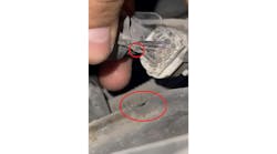
Think about this carefully: If this coil is placed anywhere other than in the cylinder No. 6 position, the integrated detection circuit will be further (in proximity) from the spark plug. The resulting induced signature will be altered due to the unintentional air gap. What are the chances the shorter, coil No. 6 is hovering over cylinder No. 3’s spark plug? Rather than invest more time in testing, a preliminary inspection of the coil placement seems much more efficient.
As can be seen from the picture above, there is the length of the shorter No. 6 coil is compared to one of the other five longer coils (Figure 10). The problem is this shorter coil is not over No. 6 (as it should be), but it is over No. 3 (our suspect cylinder). This occurred unknowingly during the recent repair noted above, so the engine had no misfires whatsoever, but the Engine Controller certainly believed so.

Misfire detection strategies of today are brilliant, but they have their flaws. For instance, something as simple as a worn axle CV Joint or even a damaged tire can skew a CKP signal enough to flag misfires.
This is nothing you haven't heard me mention before in previous articles. Understand the system strategy, reference wiring diagrams, employ the appropriate testing tools, and have a sound knowledge of what they can and cannot do. If you've got those bases covered, the rest is simply putting it all into practice.