Tool Briefing: Pinpoint emissions failure
CUSTOMER CONCERN:
A failed state emissions test for high NOX.
VEHICLE APPLICATION:
1994 Toyota 4Runner
STEPS:
- Use Lambda to determine if there are air/fuel ratio issues and if the catalytic converter has proper conditions for operation.
- Check common NOx-producing faults (i.e., EGR and timing).
- Verify O2 sensor condition.
- Directly test converter switch ratio and/or oxygen storage capacity.
- Test for exhaust leaks.
TOOLS USED:
- 5-gas analyzer
- Lambda calculator
- Snap-on Vantage Pro (a Scan Tool could also be used)
- Test adapters
- Smoke machine with O2 sensor port adapter
Before you roll your eyes at the 20-year-old vehicle in this case study, remember that Toyota has been using rear O2 sensors and rear fuel trim for many years, so this vehicle works (and fails) just like most of the later OBD II vehicles you’re seeing every day – and the same testing logic applies.
Whether you’re diagnosing a converter efficiency code (i.e., P0420, P0430) or an emissions fault, there are only two steps: verify converter operation, and verify everything else. Without verifying “everything else,” you can’t be sure the conditions are correct for converter operation, and you can’t be sure a new converter will light off and last a reasonable time. Hence, we perform a test to let some of the easiest answers direct the diagnostic path. Subsequent tests will be more informative because there was a good reason for them, and we avoid time-consuming, unnecessary tests.
This 4Runner failed an emissions test for high NOx, which could be caused by a number of faults, including: a failed converter, an EGR fault, advanced timing, lean mixture, overheating, excess head machining or carbon deposits, etc.
Lambda test
Lambda is the easiest test because we already have a failed emissions report with the necessary numbers. A Lambda value of 1.00 means the air/fuel ratio is perfect. Higher equals lean, and lower equals rich, with a desired range of 0.98 to 1.02. But even if this is a P0420 diagnosis and you don’t already have numbers, a portable 5-gas analyzer is a great place to start.
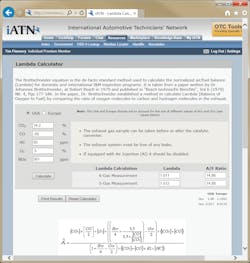
Most portable gas analyzers, like the emission tester from Automotive Test Solutions and the Kane, have a Lambda calculation built in. In this case, the emissions report does not have Lambda, so we type the numbers into the Lambda calculator found at www.iatn.net. The results show this engine running a little lean at 1.012. (See Fig. 1). That’s still in the acceptable range, but since a lean mixture adds to NOx, it’s worth looking at. The catalytic converter will “reduce” NOx into N2 and O2, but it can only do so much, and can’t reduce well if there’s already extra O2 going through the converter (like during a lean condition).
Early in the diagnosis, it’s clear that even if there’s a fault causing higher NOx and/or the converter fails, the conditions aren’t optimal for efficient NOx reduction anyway. This means the “fix” might involve finding a combination of causes.
Low-hanging fruit
Next, we could either test for the source of extra O2, or for the source of high NOx (i.e., EGR, converter, timing, etc.). We choose simple EGR function and timing tests because they only take a few minutes on this engine. Both are fine, and while there are many other possible causes, they involve more time-consuming tests, so we note potential tests we could have performed and move on.
2-for-1 tests
The next test was chosen because one test connection answers two questions. By watching the upstream and downstream O2 sensors, we test the converter as well as the sensors. For this test, you either graph O2 sensor PIDs on the scan tool or connect a lab scope. On Toyota, PIDs were extremely slow until about 2003, and non-existent before OBD II. But they do provide a handy breakout box (DLC1), so connecting a DVOM or lab scope to the O2 sensors takes only seconds. To make the connections, use blade connectors from a terminal adapter kit. Kits are available from sources like AESwave. Two adapters from the Universal Terminal Driveability Kit (AES No. 16-200) were used in this test (See Fig. 2). For applications without a breakout box, use T-pins or back probing tools to connect your test lead directly to the sensor circuit, as shown in Fig. 3.
Oxygen sensor test
One of the biggest mistakes we make is to test in the wrong conditions. Here, we need to test the O2 sensors during the failure conditions, which are on a dyno at 1,632 rpm, 50 percent load (by the state’s definition) and 15 mph. In this case, the O2 sensor signals look fine at idle, but after a short time at higher speed and load, the upstream signal range and performance degrade. The yellow trace shows the upstream signal, and the green trace shows the downstream signal (See Fig. 4). This result clearly indicates the need for an upstream O2 sensor no matter what else may be wrong.
Oxygen storage capacity
The next test is to directly check the converter. There are many methods, but we prefer checking the way onboard monitors do it (which we can do even though this OBD I vehicle does not support a converter monitor). In all converter monitors, the PCM knows how much O2 is going into the converter using the upstream O2 sensor, and how much is coming out using the downstream O2 sensor.
Different applications use different logic to process these signals:
- Switch Ratio: If the converter can store and release O2, then the downstream signal remains steady even though the upstream is cycling rich/lean. The converter stores the extra O2 during lean cycles, and uses it for oxidation of HC and CO during rich cycles. For most applications, if the downstream signal switches over 70 percent as often as the upstream signal, the converter is inefficient.
- Oxygen Storage Capacity (OSC): PCMs using this type of monitor run the vehicle rich for a few seconds at idle to empty the converter of stored O2. Then the mixture is switched lean to fill it back up again. The upstream O2 signal switches lean immediately, and the amount of time it takes for the downstream O2 signal to switch lean is the amount of O2 the converter can absorb, expressed in seconds. Most manufacturers say less than about two seconds is a failure. New converters often have between five to 15 seconds of OSC (when broken in).
The switch ratio test should be run at higher rpm after two minutes. In our 2 for 1 test showing degraded upstream O2 sensor performance (see Fig. 4), you can also see that the upstream and downstream signals have the same frequency (a 100 percent switch ratio). But this also shows the problem with the switch ratio test, and why most manufacturers’ onboard monitors now use the OSC method. Even minor mixture problems can prevent efficient converter operation and cause the switch ratio test to fail. The OSC test takes control of the mixture to give a more accurate picture of what the converter is capable of.
To perform the test, use a lab scope connection or simply graph upstream and downstream O2 sensor PIDs. After running the engine at higher rpm for two minutes, return to idle and force the mixture rich for a few seconds. Then remove the propane, and because short term fuel trim has been compensating for the propane, the mixture will automatically be lean.
The diagnosis
The vehicle needs a new converter, and to give it the best environment in which to operate, a new upstream O2 sensor.
Some OSC testing tips:
- Try graphing short term fuel trim (STFT) PIDs as well. As a starting point, add propane until STFT reaches about -20 percent.
- Don’t use so much propane that the engine stumbles, since any misfiring pushes unburned O2 into the converter, which fills it back up and defeats the test.
- Don’t introduce propane upstream of the MAF sensor – the hot wire may ignite the gas.
- If you think other conditions might be preventing the converter from getting to operating temperature, get it there yourself. For example, if Lambda is more than about 1.02, the converter may not light off, but you can give the engine bursts of propane during the pretest high rpm warmup to give it a fair chance.
- Some PCMs have very fast fuel trim adjustments, so you may have to create a small vacuum leak after the propane is removed to prevent the vehicle from going back into fuel control (upstream sensor begins to cycle) before the test is over.
This method is accurate, but you must test some known-good vehicle on your own time to get a good feel for it. Experiment with propane amounts and times to see how to get the longest OSC out of your own vehicle.
One last test
We knew that the converter was not efficient, and that the faulty O2 sensor could be the cause of the slightly lean Lambda. But exhaust leaks can also cause a false lean indication. So before selling the converter and sensor, a smoke machine is used at the downstream sensor port with the tailpipe blocked. No leaks are found, so the repair is confidently sold. If smoke is seen escaping anywhere in the system, it could cause a number of faults, depending on the exact location.
Repair verification
The DLC1 test connections are still in place, so it only takes a few minutes to warm up the new converter and test both the OSC and the new O2 sensor. Fig. 5 shows that the upstream sensor activity is much better, and the downstream activity is flat. This demonstrates that both the O2 sensor and converter make a difference.
Fig. 6 demonstrates that the OSC of the new converter is over 6.6 seconds even while “green” (many converters need about 100 miles to achieve peak performance).
The vehicle is retested for the state emissions certification and passes easily. NOX drops to “4”, and Lambda drops to “1.004,” normal for an older Toyota.