It's estimated that drivers use their vehicle's brakes 75,000 times a year. When you factor in all the wear and tear on braking system components with that level of usage, there's plenty of potential service work generated by all that braking.
This issue's Tool Q&A column touches on some key areas of brake service that readers have inquired about, with an emphasis on tools and equipment, of course.
Q: We occasionally encounter faulty vacuum brake boosters, which we usually replace when a customer complains of a hard brake pedal. Is there a more conclusive way to diagnose a booster?
A: It's easy to make a detailed test of the booster with a hand-held vacuum pump. With the engine off, disconnect the booster's vacuum hose where it connects to the intake manifold. Connect your pump to the end of the hose and draw 17 in. Hg. to 20 in. Hg. of vacuum. This may take a minute or two; you're scavenging a large chamber. The reading should hold steady. If the reading falls off, the supply hose or the booster is leaking. Check all vacuum connections for tightness and replace any bad parts. While still holding 17 in. Hg to 20 in. Hg of vacuum, have a helper apply the brakes once moderately for 30 seconds while you watch the gauge. Don't pump the pedal. You can do this test yourself by adding a piece of vacuum hose to the end of your vacuum pump. The vacuum should drop off no more than 6 in. Hg immediately after you apply the brakes and should change no more than 2 in. Hg during the 30-second period. Replace the booster if it fails to pass either of the tests described here.
Q: To save labor, we're considering an on-car brake lathe. Are there any new developments in this area?
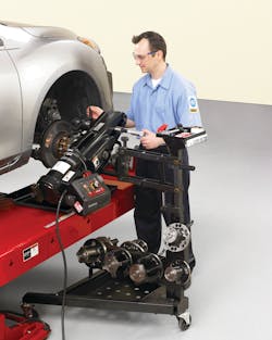
A: Yes, one of the latest breakthroughs in on-car lathes features faster and easier setup to enhance overall service. A two-way adjustable compensation adaptor that works with computerized compensation adjusts for lateral runout of the hub in seconds. This capability allows for shops to refinish rotors within OEM specifications in a matter of minutes. Other advancements include ACT (Anti-Chatter Technology) to minimize finish irregularities by virtually eliminating chatter. ACT oscillates the speed of the lathe to prevent the buildup of vibration that can occur on any fixed-speed lathe, ensuring a smooth surface finish. ServoDrive technology also enables you to vary the spindle speed and rotational torque of the lathe while in operation. This unique ability allows “on-the-fly” speed adjustments without compromising the final surface finish. Also, reverse rotation proves beneficial when servicing some vehicles with limited-slip differentials, which produce excessive drag on the driveshaft, preventing normal lathe operation.
Q: With more emphasis on brake fluid replacement, we're looking for a way to make this job easier. What are our options?
A: Brake bleeding becomes a single-person job if you use a pressure or vacuum bleeder. When shopping around, consider which adapters are included and which ones are optional. As an interesting new twist on vacuum bleeding, one company offers reverse-flow technology in its tool. Rather than drawing fluid and air down and away from the master cylinder, this vacuum bleeder pulls fluid and air upwards towards the master cylinder, which is the direction air naturally wants to travel in the first place. Don't forget that you may also need several special bleeder wrenches for the cars you service, to ease access to the bleeder fittings. Finally, remember to use the recommended brake fluid for the vehicle you're servicing. While most cars use DOT 3 fluid, there are enough cars using DOT 4, so take note.
Q: We need rotor refinish specifications and a means of comparison to those specs. Can you help?
A: Although OEM requirements vary, a rotor finish of 20 to 50 micro-inches Ra (roughness average) is generally acceptable. Sources on the aftermarket side of things, however, broaden that range a bit and state that anything from 15 to 80 micro-inches is OK. GM says resurfaced rotors should have a surface finish of 60 micro-inches or less. GM also recommends applying a non-directional swirl finish to the rotors after they've been resurfaced, using 120-grit aluminum oxide sanding discs. 150-grit aluminum oxide sandpaper can also be used. To achieve this surface finish, sand the rotors for 60 seconds using moderate pressure. GM, along with Ford, Toyota, Nissan and some others give the OK to a one-step method that uses a lathe that operates with a fixed spindle speed of 105 rpm and a fixed crossfeed rate of .003 in. (0.076 mm) per revolution. A moderate spindle speed, when combined with the slow crossfeed speed, renders a surface finish ranging from 10 to 50 microinches, no matter what the depth of cut is. Remember, there are operating differences between the various manufacturers’ brake lathes, so follow the lathe manufacturer’s recommendations at all times. Should the spindle speed (called drive speed with on-the-car resurfacers) or crossfeed speed be excessive, you can wind up “threading” the rotor. A feed rate that’s too slow can also cause problems. For instance, too slow a crossfeed can result in a rubbing of the surface, resulting in a unsatisfactory finish. Of course, your lathe’s tool bits must be sharp at all times in order to achieve the desired surface finish.
Q: We used to turn away pad replacements on cars with rear disc brakes because of having to retract the caliper pistons. Is there a tool to make this easier?
A: You certainly don't want to send this lucrative service work away. Numerous companies offer tools that help to rotate the caliper pistons back into the housing, thereby providing the clearance needed for new pad installation. Some kits fit a wide range of cars such as Audi, Chrysler, Ford, GM, Honda, Jaguar, Mazda, Mini Cooper, Mitsubishi, Nissan, Saturn, Subaru, Toyota, Volkswagen and Volvo. Remember to always follow the exact steps outlined in a reliable shop manual when servicing rear disc brake systems.
Q: One of our techs says that measuring rotor thickness with a standard micrometer is fine. A different tech says that we need a different tool for measuring rotor thickness. Who’s right?
A: The correct tool for measuring rotor thickness is a rotor micrometer. While substantially the same as a standard micrometer, a rotor micrometer has one flat anvil and one pointed anvil. The pointed anvil allows the micrometer to reach into any grooves on the rotor surface, whereas a flat anvil would ride up on the shoulder over the groove. As such, the rotor micrometer provides more reliable readings of rotor thickness, a critical part of brake inspection. Remember, when measuring rotor thickness, measure at eight different locations around the rotor’s overall diameter. Then, compare the actual thickness to the minimum thickness specifications cast on the rotor or the minimum thickness specs published in a reliable source of service information.
Q: When tracking down ABS problems, what tools do we need?
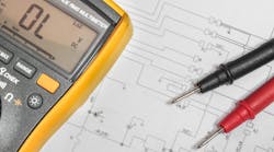
A: Diagnosing Antilock Brake System problems closely resembles tracking down diagnostic trouble codes in a powertrain control module. Connect a scan tool to read whether any ABS codes are present; some ABS problems occur without ever setting a code. Then, check service information for the nature and description of any codes and perform pinpoint tests as recommended. Using a Digital Multimeter (DMM) with a frequency counter, measure the sensor signal at the sensor connector and also at the connector to the computer as needed. Getting a good handle on sensor output is also a great use for a lab scope, so this is a great application for a stand-alone or combo scope. To ease connection of your equipment, carefully back-probe connections or connect jumper wires as needed, using caution not to damage any connections. On some applications, you may also need a breakout box or test harness to read sensors. If possible, operate the sensor through its full range and check the signal at several points. Next, compare your sensor readings to the operating range charts found in service information. Based on this, you should be able to get to the heart of an ABS problem fast and make the proper repairs.
Q: A shop manual calls for checking an ABS wheel speed sensor’s bias voltage. What is it and how do we measure it?
A: The speed sensor’s bias voltage enables fault detection in the sensor circuit and also raises the voltage to help reduce signal interference. The voltage varies depending on manufacturer, but is often the typical 5-volt reference found in other computer circuits. You can measure bias voltage easily with your Digital Multimeter (DMM) by following the connection points outlined in service information.
Brake service opportunities abound with almost infinite possibilities. Whether mechanical, hydraulic, electrical, or electronic in nature, you can be assured that the right brake system service tools will help you capitalize on all those possibilities.


